3o|||sheet is a universal software environment for developing applications for Programmable Logic Controllers (PLCs).
- Hardware Independence
- Integrated Development Environment (IDE)

3o|||sheet is a universal software environment for developing applications for Programmable Logic Controllers (PLCs).
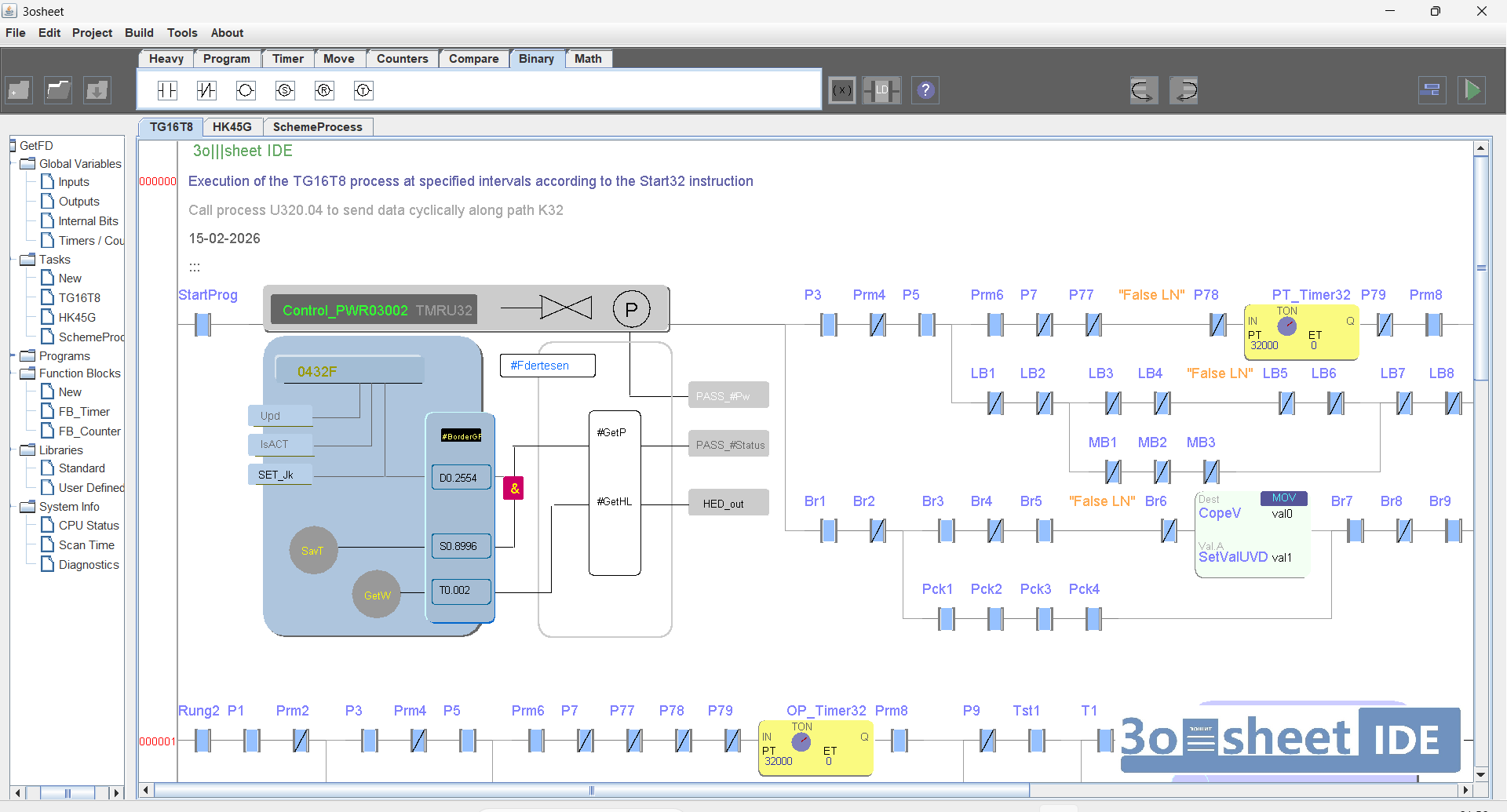
A lightweight, cross-platform IDE built on OpenJDK. Runs on single-board computers with minimal resources.
Supports LD, FBD, and ST languages plus a virtual machine instruction set for advanced logic design.
Offers extensive debugging capabilities: developers can modify code in real-time without physically restarting the PLC.
The development environment can create executable programs for the PLC in two modes:
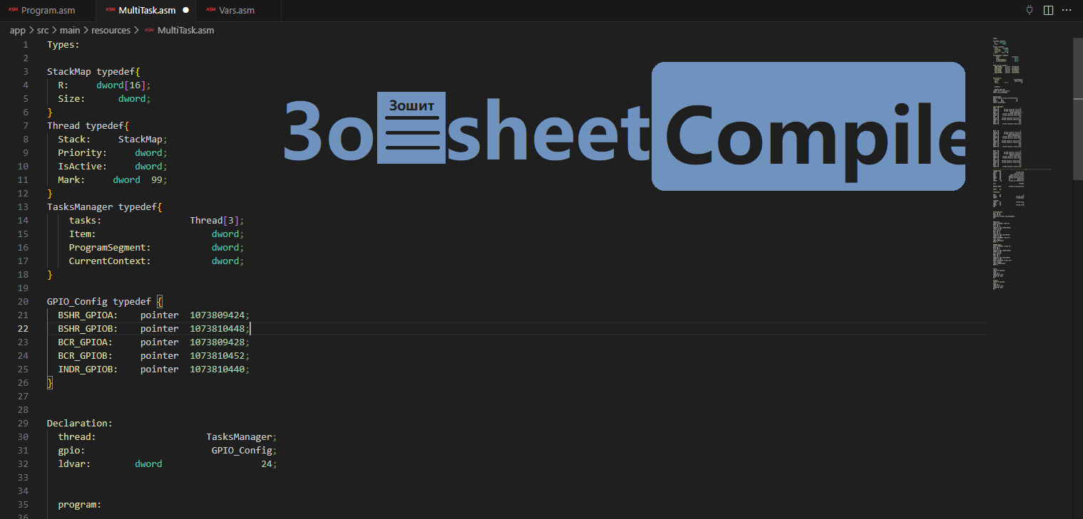
Is a standalone application that compiles text programs written in LD, FBD, ST and .3osheet into executable bytecode for a virtual machine.
The compiler can be integrated into third-party development tools (for example, Visual Studio, etc.).
It includes a complete set of tools for working with complex custom variables, virtual stack, and context management, enabling the development of sophisticated recursive algorithms and multithreaded tasks (coroutines).
Register-based Virtual Machine running safely in a sandbox. Works on devices with only 8 KB RAM and full peripheral access.

The system supports two modes of operation: either the execution of multiple independent contexts (virtual machines running distinct programs) or a single program operating in DME mode with N replicas
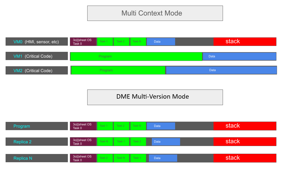
The platform incorporates a unique divergent architecture designed for maximum reliability and fault tolerance in safety-critical applications. Divergent Multi-Version Execution (DME) is a runtime semantic consistency verifier for diversified executions. Each replica is compiled independently, producing distinct physical code and data memory layouts while preserving identical opcode-level semantics and isomorphic control-flow graphs. Faults are detected by comparing canonical instruction traces—including opcodes, register identifiers, loaded/stored values, and computed results—while explicitly discarding layout-dependent addresses. The approach targets bare-metal embedded systems without an MMU, particularly 32-bit controllers. DME transforms low-level correlated perturbations into observable semantic divergence or structural address-space collapse without altering program semantics.
Unique protection mechanisms of Divergent Multi-Version Execution architecture that standard redundancy schemes cannot provide.
| Threat or System Requirement | Standard Lockstep / TMR | DME Superiority ✨ |
|---|---|---|
|
Highly Correlated Faults (EM pulses, radiation, voltage glitches) |
DEFENSELESS A single perturbation shifts all replicas identically. The system accepts the failure as correct. |
Absolute Protection Driven by complementary branch signs and NOP-decorrelation, identical faults force replicas onto divergent semantic paths. Instant detection! |
|
Control-Flow Hijacking (Return address corruption, buffer overflows) |
BLIND SPOT If the corrupted address falls within an allowed region, all replicas transition simultaneously. |
Zero-Latency Intercept Our Address Non-Aliasing layer halts execution the exact millisecond cross-replica addresses collapse, long before any bad data spreads. |
|
Software Bug Resilience (Null pointer dereference, "wild" pointers) |
UNSUPPORTED Logical software bugs replicate across identical architectures without triggering flags. |
Runtime Semantic Validation Accidental value-as-pointer assignments trigger immediate address-space collapse detection. DME acts as a live validator for pointer semantics. |
|
Hardware Costs & Constraints (Requirements for high-end cores and MMUs) |
HIGH DEPEDENCY Demands specialized, expensive multi-core chips with heavy silicon overhead. |
Hardware Agnostic Designed natively for bare-metal, low-cost 32-bit controllers (e.g., ARM Cortex-M class) without virtual memory (MMU). Entirely managed at compile time. |
Measured execution times for boolean and Integer and floating-point operations on different microcontrollers and PLCs.
| Device | Boolean Operation | Integer / Floating-Point Operation |
|---|---|---|
| STM32G030 64Mhz (3o|||sheet Runtime) | 1.0 μs | 3.6/24 μs |
| STM32F103 72Mhz (3o|||sheet Runtime) | 1.1 μs | 3.2/16.6 μs |
| STM32F407 168Mhz (3o|||sheet Runtime) | 0.6 μs | 1.8/1.8 μs |
| CH32V203 (144Mhz Mode) (3o|||sheet Runtime) | 0.8 μs | 2.1/18.3 μs |
| CH32V307 144Mhz (3o|||sheet Runtime) | 0.8 μs | 2.0/2.0 μs |
| Rockwell Micro810 | 2.5 μs | 8.6/ - μs |
| Rockwell Compact GuardLogix 5380 1Ghz | ~0.01–0.05 μs | ~0.01–0.08 μs |
| Siemens S7-1200 | ~0.08μs | ~2.3μs-4 μs |
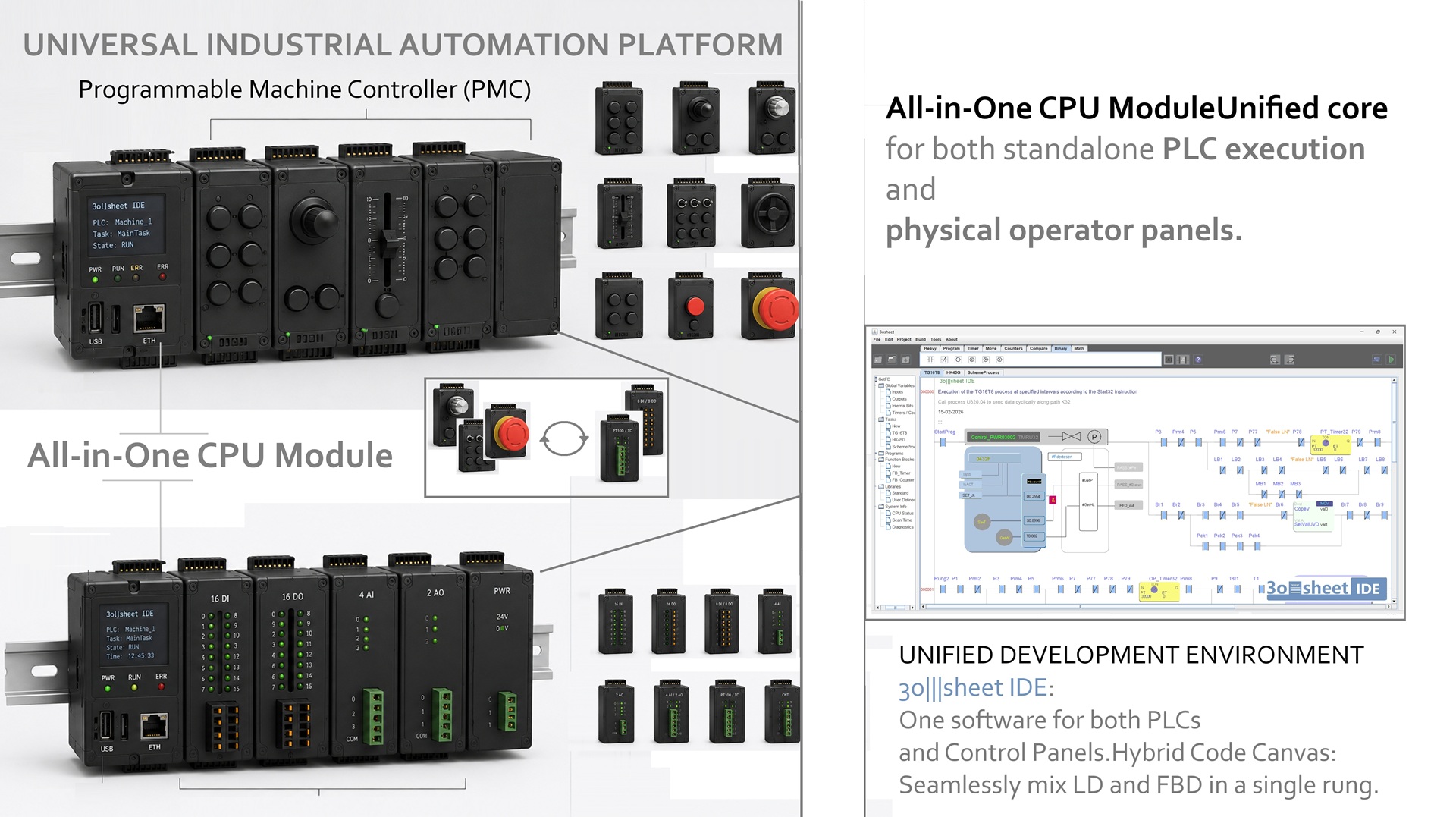
The Programmable Machine Controller (PMC) represents an unprecedented, industry-first hardware-software ecosystem that completely redefines traditional industrial automation interfaces. Traditional setups strictly segregate machine control logic (the PLC) from operator terminal interfaces (HMI panels) and standard peripheral I/O cards, forcing them to exchange data over slow, cyclic network communication layers. This separation causes significant software latency, data packet arbitration, and deterministic processing jitter.
The PMC breaks this paradigm through its proprietary Unified Core Architecture. It seamlessly merges the industrial computing core, standard field expansion I/O, and physical high-ergonomics operator controls (buttons, analog joysticks, rotary encoders, and switches) into a single, unified execution and mechanical layer on a standard DIN rail. By eliminating intermediate communication barriers, the controller achieves complete architectural fusion.
To coordinate execution-critical physical controls alongside standard digital data traffic on a shared interface, the platform incorporates the GARM structural principle. GARM explicitly splits real-time control mechanics into two autonomous, parallel operational planes that interact asynchronously without blocking one another:
The unified physical backbone comprises a specialized shared signal fabric containing a fixed pass-through bundle of 36 to 72 dedicated raw conductors alongside an independent digital protocol line. When an ergonomic operator block or standard high-density I/O module docks onto the common rail system, it initiates an automated Zero-Protocol Mapping handshake:
To safeguard system stability, optimize conductor utilization, and enforce deterministic timing bounds, the PMC system strictly classifies all incoming runtime signals into three dedicated architectural tiers:
| Execution Tier | Physical Bus Routing | Verification Strategy |
|---|---|---|
| Critical Execution Tier (e.g., E-Stops, Safety Interventions) |
Direct hardware potential matrix via the 36-72 physical conductor lines. | Asynchronous 10-100 ms status heartbeat over digital channel for post-factum logging. |
| Important Execution Tier (e.g., Operational Joysticks, Dials) |
Direct hardware potential routing straight into core CPU terminal registers. | Processing status feedback loop returned via digital channel within execution scan. |
| Ordinary Execution Tier (e.g., Thermocouples, Backlights) |
Exclusively packetized and transmitted via serial digital bus; consumes 0 wire resources. | Fully encapsulated synchronous or asynchronous communication protocol transactions. |